


 HOME
HOME

-

How to choose the appropriate substrate for ceramic circuit boards?
2023 11,16 -
Laser Cutting or Water Saw Cutting? How To Choose the Best Cutting Solution for Ceramic Circuit Boards
2023 11,13 -
Why Ceramic PCB Is So Expensive?
2023 11,10 -
Which Process Ceramic Circuit Board Is A Better Solution For Semiconductor Refrigerator Chips?
2023 11,06 -
Silicon Printing Circuit Boards For Advancing Electronics
2023 10,27 -
What is the Difference Between HTCC and LTCC Ceramic PCB
2023 10,06 -
What is the Difference Between 96% and 99% Aluminum Oxide in Ceramic PCBs?
2023 09,20 -
Why thick film ceramic PCB is good for oil level sensor in automotive industry?
2023 08,25 -
Statistical analysis of ceramic PCB application fields
2023 08,16 -
Notice of anti-static requirements for PCBA processing and production
2023 08,16 -
Silver Paste: The Best Conductor Material for Via Holes in Thick Film Ceramic Boards
2023 08,16 -
Testing Circuit Board Ceramic Diode Fuses: A Complete Guide
2023 08,07 -
Why DBC is replaced by DPC in ceramic PCB manufacturing?
2023 08,01 -
What is thick film ceramic PCB?
2023 08,02
Testing Circuit Board Ceramic Diode Fuses: A Complete Guide
Introduce
Testing a circuit board ceramic diode fuse can be a daunting task for a novice. However, it is a critical step in ensuring the safety and functionality of electronic devices. This guide will walk you through the process of testing a ceramic diode fuse on a circuit board, including the tools you'll need and what to look out for while testing.
Tools you need
Before you start testing ceramic diode fuses, you'll need to gather some basic tools:
1) Multimeter
2) Iron
3) Solder wire
4) Solder braid
5) Small pliers
Learn About Ceramic Diode Fuses
Ceramic diode fuses are small cylindrical components used to protect electronic equipment from power surges and other electrical problems. They are designed to break a circuit when the voltage exceeds a certain level, preventing damage to other components on the board. However, ceramic diode fuses fail over time, so they must be tested periodically to ensure they are functioning properly.
Testing Ceramic Diode Fuses
Here's how to test a ceramic diode fuse on a board:
Step 1: Turn off the power
Make sure the power is off and the device is unplugged from the power source before testing the ceramic diode fuse. This step is critical to prevent any electric shock or accident.
Step 2: Locate the Ceramic Diode Fuses
Using a schematic or datasheet, locate the ceramic diode fuse on the board. These fuses are usually marked with the letter "D" followed by a number.
Step 3: Set the multimeter to diode mode
Set the multimeter to diode mode. A diode pattern is indicated by a symbol that looks like an arrow pointing towards a vertical line.
Step 4: Test the Ceramic Diode Fuses
Using small pliers, remove the ceramic diode fuse from the circuit board. Place the multimeter probes across the two terminals of the ceramic diode fuse. The multimeter should show a voltage reading between 0.6V and 0.7V. If the multimeter reads "OL" or "0," the ceramic diode fuse is faulty and needs to be replaced.
Step 5: Replace the failed ceramic diode fuse

If you find a ceramic diode fuse has failed, it needs to be replaced. Use a soldering iron and desoldering braid to remove the old ceramic diode fuse and replace it with a new one. Make sure the replacement ceramic diode fuse has the same voltage and amperage rating as the old one.
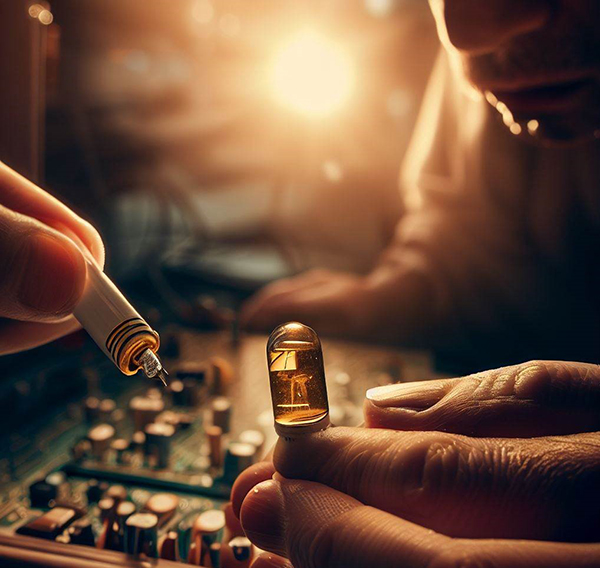
Test Board Ceramic Diode Fuses
Frequently Asked Questions About Ceramic Diode Fuses
Ceramic diode fuses can fail for a number of reasons. Here are some common problems you may encounter when testing ceramic diode fuses:
1) Overheat
2) Overload
3) Age-related wear and tear
4) Incorrect voltage or current rating
Tips for Testing Ceramic Diode Fuses
Here are some tips to keep in mind when testing ceramic diode fuses on a circuit board:
1) Always turn off the power before testing ceramic diode fuses.
2) Use a schematic or datasheet to locate the ceramic diode fuse on the board.
3) Make sure the replacement ceramic diode fuse has the same voltage and amperage rating as the old one.
4) Use a multimeter to test ceramic diode fuses.
5) If a ceramic diode fuse fails, replace it immediately to prevent damage to other components on the board.
6) Ceramic Diode Fuses
In conclusion
Testing ceramic diode fuses is an important step in ensuring the safety and functionality of electronic equipment. Following the steps outlined in this guide, you can easily test the ceramic diode fuse on your board and isolate any issues. When testing ceramic diode fuses, remember to use proper tools, turn off the power, and follow safety procedures.
Common problem
What are ceramic diode fuses used for?
Ceramic diode fuses are used to protect electronic equipment from power surges and other electrical problems. They are designed to break a circuit when the voltage exceeds a certain level, preventing damage to other components on the board.
How do I test a ceramic diode fuse on a circuit board?
To test a ceramic diode fuse on a circuit board, you'll need a multimeter, soldering iron, solder wire, desoldering braid, and small pliers. You should also follow safety protocols and turn off the power before testing.
What should I look out for when testing ceramic diode fuses?
When testing a ceramic diode fuse, you should look for a voltage reading between 0.6V and 0.7V on the multimeter. If the multimeter reads "OL" or "0," the ceramic diode fuse is faulty and needs to be replaced.
Why do ceramic diode fuses fail?
Ceramic diode fuses can fail for a number of reasons, including overheating, overloading, age-related wear, and incorrect voltage or current ratings.
Can I replace the ceramic diode fuse myself?
Yes, you can replace a ceramic diode fuse yourself, but it's important to follow safety procedures and use the proper tools. Make sure the replacement ceramic diode fuse has the same voltage and amperage rating as the old one.
 Products
 About us
 Contact us


