


 HOME
HOME

-

LTCC PCB Surprises: What Most People Miss
2025 12,09 -
Step-by-Step Guide to DPC PCB Design for Sensor Systems
2025 12,03 -
Ceramic PCBs Essential Benefits and Applications
2025 12,01 -
How Al2O3 DPC Ceramic Substrate PCB Enhances Heat Dissipation in Modern Electronics?
2025 11,28 -
How to Choose Between Ceramic, FR4, and Metal Core PCBs
2025 11,27 -
DPC Ceramic PCB Materials: Surprising Science Inside
2025 11,26 -
Wire bondable 2-layer Alumina substrates PCB | Bstceramic PCB
2025 09,22 -
Silicon Nitride Substrate, Silicon Nitride Ceramic Substrate Formula
2025 05,08 -
What is thick film ceramic PCB?
2023 08,02
What is the Difference Between HTCC and LTCC Ceramic PCB
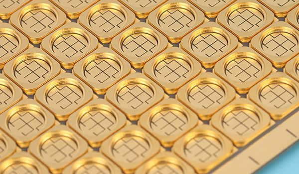
Co-fired multi-layer ceramic substrate PCB is made by several single-layer substrates by lamination, hot pressing, degreasing, sintering and other processes. Due to it can be made into multi-layer circuits, it has higher density traces and longer interconnect length. It can be shortened as much as possible and improve the assembly density and signal transmission speed, so as to meet the requirements of circuit miniaturization, high density, multi-function, high reliability, high speed and high power. Among them, the co-fired multi-layer ceramic substrate gradually used in high-power device packaging because it can be burned into electrode materials, substrates and electronic devices at one time to achieve a high degree of integration.
The co-fired multi-layer ceramic PCB is widely used in high-power devices, especially in the 3rd generation semi-conductors because of its excellent thermal conductivity, low CTE (coefficient of thermal expansion), good mechanical strength.
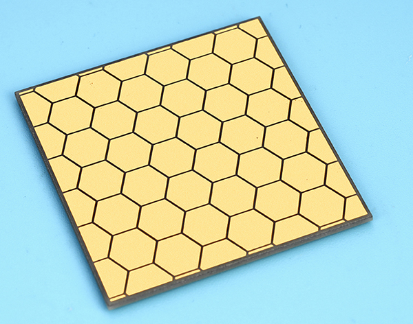
What is Co-fired Ceramic PCB?
Multilayer ceramic substrate technology originated from the development of the American Radio (RCA) company in the late 1950s, and the current basic process technology (sheet manufacturing technology with the casting method, through hole formation technology and multilayer lamination technology) has been applied at that time. The main computer circuit board multilayer substrate commercialized in the early 1980s was co-fired with alumina insulation and conductor materials (Mo, W, Mo-Mn) at 1600°C, that is, high temperature co-fired ceramics (HTCC). With the development of communication to high frequency and high speed, in order to achieve low loss, high speed and high-density packaging, low temperature co-fired ceramics (LTCC) came into being. Today we will learn the difference between HTCC and LTCC.sd
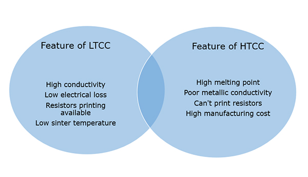
What is Difference Between HTCC and LTCC?
Though HTCC and LTCC like a couple of co-twins, they still have some differences in some aspects.
1. Conductor material difference
In order to ensure high sintering density under low temperature co-fired conditions, amorphous glass, crystallized glass, and low melting point oxides are usually added to the components to promote sintering during the LTCC manufacturing. Glass-ceramic composite material is a typical low-temperature co-fired ceramic material. The conductors used are highly conductive materials (such as Ag, Cu, Au and alloys, such as AG-PD, AG-PT, AU-PT, etc.).
High temperature co-fired ceramic materials are mainly alumina, mullite and aluminum nitride ceramics, HTCC ceramic powder does not add glass material. And the conductor paste is made of tungsten, molybdenum, manganese and other high melting point paste.
| Ceramic PCB | Ceramic Substrate | Conductor | ||
| Material | Sinter Temp/C | Material | Melting Point/C | |
| LTCC PCB |
Glass/Ceramic Composite Crystal Glass Crystal Glass/Ceramic Composite Liquid-phase Sintered Ceramics |
900-1000 | Cu | 1083 |
| Au | 1063 | |||
| Ag | 960 | |||
| Ag-Pd | 960-1555 | |||
| Ag-Pt | 960-1186 | |||
| HTCC PCB |
Alumina Ceramic Mullite Aluminum Nitride |
1600-1800 | Mo | 2610 |
| W | 3410 | |||
| Mo-Mn | 1246-1500 | |||
2. Sinter temperature difference
The manufacturing processes of HTCC and LTCC are basically the same, we can call them a couple of co-twins. The typical process includes casting, cutting, punching, filling, printing, hot pressing, sinter and so on. Due to the selection of different materials to make the sintering temperature is different, HTCC is generally sintered at high temperature above 1500°C, and LTCC sintering temperature is generally below 1000°C.
3. Application difference
LTCC uses Au, Ag, Cu and other metals with high conductivity and low melting point as conductor materials. Due to glass ceramics have low dielectric constant and low loss performance at high frequency, makes LTCC a very suitable for application in RF, microwave and millimeter wave devices.
| Application | Specific Product |
| Module | Front-end Module |
| Receiving Module | |
| Automotive Power Control Module | |
| Package/Substrate | PA Module |
| Surface Wave Device Packaging | |
| SMD | BRF |
| LPF | |
| Coupler | |
| Duplexer | |
| Antenna |
However, because of the high sintering temperature of HTCC, it can’t use gold, silver, copper and other low melting point metal materials like LTCC, must use tungsten, molybdenum, manganese and other refractory metal materials. This kind of materials features in low conductivity, will cause signal delay and other defects in some aspects. So, it is not suitable for high-speed or high-frequency micro-assembly circuit substrate. But HTCC substrate has the advantages of high structural strength, high thermal conductivity, good chemical stability and high wiring density, so it has a wide application prospect in high-power micro-assembled circuits. Below is a performance table of HTCC and LTCC.
| Item | HTCC | LTCC |
| Material | Alumina, AlN, Mullite | Crystaline Ceramics, Alumina, SiO |
| Sinter Temp | 1500-1800℃ | 850-900℃ |
| Conductor | W, Mn, Mo | Au, Ag, Cu, Pt |
| Thin Layer Resistance | 8-12mΩ/cm | 3-20mΩ/cm |
| Dielectrical Constant | 8-10 | 5-8 |
| Resistance | Not Available | 0.1Ω-1Ω |
| Sintering Shrinkage Rate (X,Y) | (12-18)% | (12.0+/-0.1)% |
| Sintering Shrinkage Rate (Z) | (12-18)% | (17.0+/-0.1)% |
| Line Width | 100um | 100um |
| TH Diameter | 125um | 125um |
| Metal Layer | 8 or 63 | 33 |
| Thermal Conductivity | 180-200W/m.k | 2-6W/m.k |
Above all are the introduce of HTCC PCB and LTCC PCB, hope this can make you sense the differences between them. Welcome to contact us if you have other questions.
 Products
 About us
 Contact us


